Before we start talking about a resistor in electricity as a general or in electrical and electronics one has to know that there are two types of electronic components these being;
Passive components being electronic components that reduce or limit the output of an electric circuit e.g. resistors, inductors etc while Active components are the ones that are used to rectify power or produce there out electrons flow like the semiconductors e.g. diodes, transistors etc.
So, after knowing that a resistor is a passive electrical component lets dive straight into the main point of this article which is all about how resistors help and are used in an electrical circuit.
A resistor is a passive two-terminal(pin) electrical component that performs various uses and applications on a circuit these include;
A resistor is used to reduce current in a circuit from a large amount and appropriate value a certain device of component can easily use with out burning, this is done by connecting the device in series with the resistor so that the resistor drops down the voltage to the devices voltage rating giving it the current it can use without burning and the rest is dissipated in the resistor as heat energy, according to ohms law.
Consider a light emitting diode (LED) that is rated 2volts,20mA and you connect this resistor to a 9volts battery direct without a resistor this LED is going to burn because the voltage supplied is way over the normal voltage of the light emitting diode now to avoid this incident of the LED burning out we get the voltage rating of the LED and subtract it from the supply voltage and that gives the voltage that will be dropped by the resistor and then use that voltage to determine the value of the resistor that will be connected in series with the light emitting diode. That is to say;
(Vs-Vled)/Iled=R
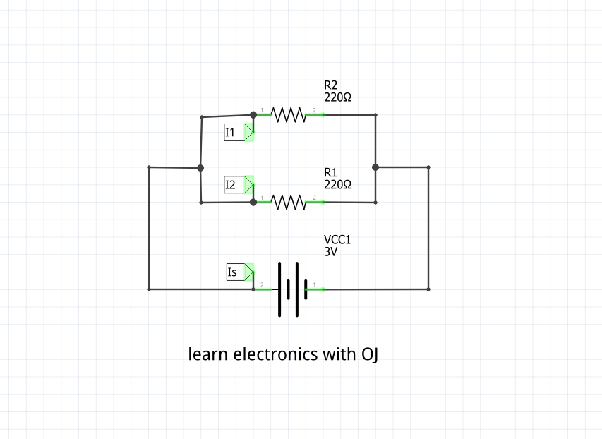
Resistors are also commonly used to divide the supply voltage and supply it to different parts of the circuit since different circuit components use different voltage values and ratings, this is done by connecting several resistors in series this maintains the circuit current but at each resistor terminal a voltage is dropped by that particular resistor and this done is accordance to Kirchhoff’s voltage law.
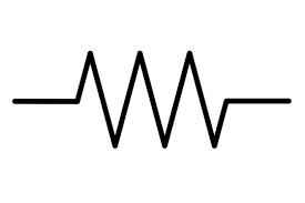
In this case several resistors are connected end to end that is to say in series and different voltages are given out at the last end of the resistor chain but all these voltages show be equal to the supplied voltage as Kirchhoff’s voltage law states, so if different voltages are need different resistor values are used but if the aim is to half the voltage every time after each resistor then resistors with same value is use if the first resistor is 1KΩ then all should be 1kΩ in order to half voltage very time. That is to say,
Take two resistors connected to divide voltage that is the formular for the voltage between the resistors.
(R1/(R1+R2))Vs=Vout
In transmitting alternating current (AC) lines large resistor up to thousands of mega ohms are used to dissipate the large voltage coming from the source and this gives a voltage different between the incoming and leaving voltage since the resistor dissipates some current as heat which is registered by the system avoiding a short circuit in case no load is connected to the system.
Just like in the AC transmition lines some time resistors are used as load if we don’t have anything to connect on the circuit or when we are trying to design out a system and we are testing out different load resistances of the system, we can connect different resistor values at the output to see different current drops at different components on the circuit. This more so when you’re designing out a power supply.
Apart from the functions talked of above resistor are mostly and commonly configured on boards, these connections are used as signal path to microcontrollers and micro-processors and they include;
In this connection the resistor connects a given output or input to the positive power (VCC) and the voltage reference point is tapped between the resistor and ground this connection is mostly done when a chip or micro-controller reset using a positive volage that is to say the chip is highly reset. For example;
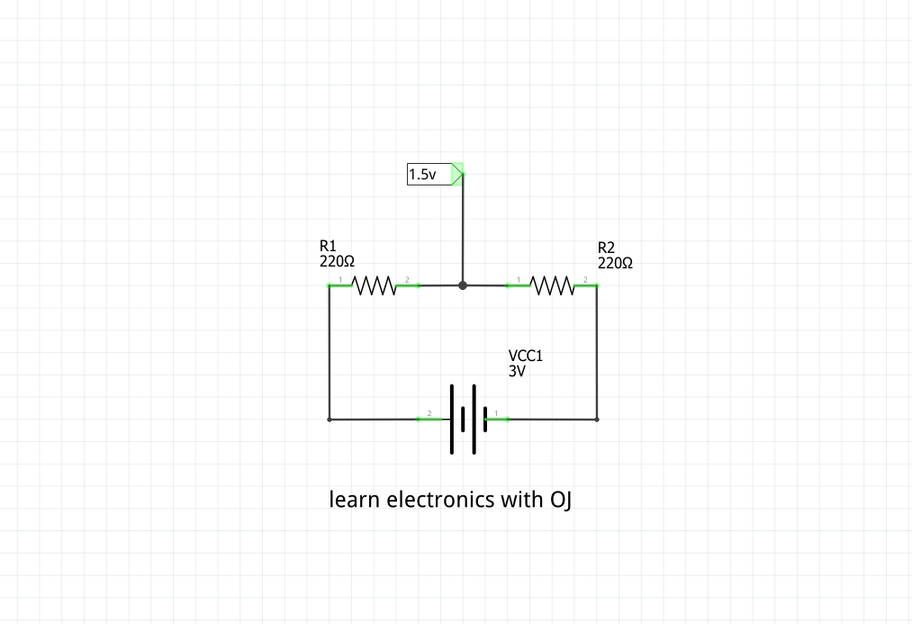
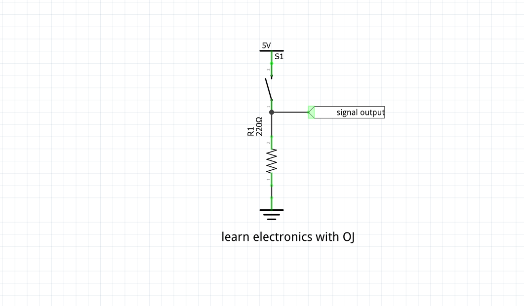
Just like the pull-up the pull down just connects a given output or signal to ground (GND) that is to say the resistor provides a path of current from positive to ground and signal is tapped between ground and resistor. For example.
The most common faults that resistors get in circuits is open circuit faults this is when a resistor burns and opens disconnecting the given component from power supply but other faults also include burning out over heating and breaking off and lastly change of value that is to say a resistors which was 1kΩ becomes 600Ω because the materials that made it are getting old with time.
To sum up all the article resistors are one four major electric components that is used for current division, voltage division, current limiting pulling up and down a given microcontroller pin and generally provide current and voltage to different circuit parts and regions as explained above.